Conveyor Sections (Steps 32 - 34)
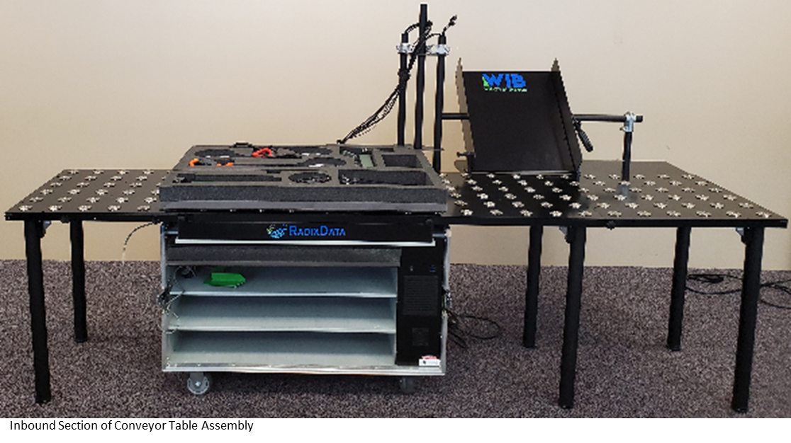
Remove the Inbound Conveyor Table Section from
the base by unscrewing with two (2) Seven-Lobed Knob – conveyor section
fasteners. Store the two (2) Seven-Lobed Knob – conveyor section fasteners in
the Compartment 8 of the Tools and Small Parts Box. Pull the Inbound Conveyor
Section free and lay the section on the ground roll balls face down. Unlock the
table legs and gently fold them until they click into the folded locked
position. The legs may require screwing in the bottoms. Store the Inbound
Conveyor Section on the bottom shelf. Store the paddles on top of the conveyor section.
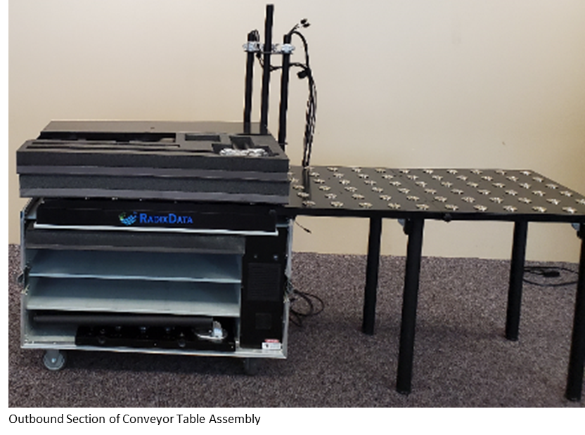
Remove the Outbound Conveyor Table Section from
the base using the 3/16” (White) Hex key by unscrewing the Hex Cap Screw from
the back of the unit where the Outbound Section is secured to the Stadium
Section of the Conveyor. Store the Hex Cap Screw Compartment 3 of the Tools and
Small Parts Box. Remove the Seven-Lobed Knob – conveyor section fastener from
the front of the Outbound Conveyor section where it is secured to the Stadium
Conveyor Section. Store the Seven-Lobed Knob – conveyor section fastener in
Compartment 8 Tools and Small Parts Box. Pull the Outbound Conveyor Section
free and lay the section on the ground roll balls face down. Unlock the table
legs and gently fold them until they click into the folded locked position. The
legs may require screwing in the bottoms. Store the Inbound Conveyor Section on
the middle shelf.
Remove the Stadium Conveyor Table Section from
the base by unscrewing with two (2) Seven-Lobed Knob – conveyor section
fasteners. Store the two (2) Seven-Lobed Knob – conveyor section fasteners in
the Compartment 8 of the Tools and Small Parts Box. Pull the Stadium Conveyor
Section free and lay the section on the ground roll balls face down. Unlock the
table legs and gently fold them until they click into the folded locked
position. The legs may require screwing in the bottoms. Store the Inbound
Conveyor Section on the bottom shelf.
Related Articles
Support Brackets and Arm (Steps 35 - 41)
Step 35 – Place Front Cover on Top of Layer 1 of Foam Packing Tray Retrieve the Front Cover from the Lid. Place the Front Cover on top of the Foam Packing Tray with the latch away from you. Step 36 - Remove the Side-Mounted Support Bracket from the ...
Table Extensions (Steps 28 - 29)
Step 28 – Remove Table Extension Fasteners & Support Bar Fasteners Using the 3/16” Hex Key (White) remove the two (2) hex screws securing the table extension to the conveyor section. The Screws securing the table extension can be found in each corner ...
Remove Barcode Scanner (Steps 22 - 23)
Step 22 - Uninstall Barcode Scanner Cradle Using the 5/32” Hex Key, remove the barcode scanner mount from the inbound conveyor section. Step 23 – Unplug and Store Barcode Scanner Unplug the Barcode Scanner from the USB Port labeled Barcode which is ...
Table Extension Support Bars (Steps 30 - 31)
Step 30 – Disassemble Table Extension & Stadium Ramp Support (Backstop) Bars Using the 6mm (Grey), loosen the hex screws securing the Stadium Ramp Support Bar to the Table Extension Support bars. These are the Hex Screws located below the Stadium ...
Unplug WIB Unit and Peripherals (Steps 1 - 4)
Step 1 - Disconnect the cords Unplug the cords from the labeled ports on the back of the WIB™ Unit. Step 2 - Unplug Monitors and Top/Aerial Camera Unplug the Power, USB 3.0 B-Male and HDMI cables from the back of the monitors. Refer Monitor Cable ...